Arduino WiFi Module ESP8266 NodeMCU Tutorial | Wireless Messaging
Programming 2 ESP8266 NodeMCU Modules to communicate

To start using the NodeMCU with your Arduino IDE, follow the 5 minute setup process detailed in this article.
Introduction
This post will show you how to use the HTTP protocol between two ESP8266 NodeMCU devices and get them to talk to each other over a local WiFi network.
HTTP is the most basic and universal communication protocol between devices on the internet or a LAN connection. This is the protocol used by browsers to open webpages when you surf the internet.
It is also the easiest to implement while coding on Arduino.
To get a little more comfortable with the use of HTTP communication on the NodeMCU, first try this example on Surfing the Internet with the ESP8266. This example shows you how the NodeMCU can open websites in the form of text, using the HTTP protocol.
In the HTTP protocol, there is one Server and multiple Clients. The Server is the device that stores the information and the Clients are the devices that request the information from the Server based on the User commands. For example, in the case of web surfing, your browser on your Smartphone or Laptop is the Client and the Website Host (eg. www.Google.com) is the Server.
 |
| Using the NodeMCU Dual Kit for this example |
How this will work
We will be using 2 NodeMCU Modules :
- NodeMCU 1 - will work as a Server
- NodeMCU 2 - will work as a Client

Instead of allowing an external website host to be the Server, we will be programming NodeMCU 1 to take that role. NodeMCU 2 will act as a Client, similar to the one in the example of Surfing the Internet.
NodeMCU 2 will send requests to NodeMCU 1, and will receive responses from it, just like a website server.
NodeMCU 1 can send responses based on parameters within the request from NodeMCU 2, and NodeMCU 2 can execute functions like switching LEDs based on the response from NodeMCU 1.
This is a good example of how IoT works in practice.
Setting up this System
- Have the 2 NodeMCUs ready with their USB cables
- Designate NodeMCU 1 as the 'Server', and NodeMCU 2 as the 'Client'
- Now go to the Github page and grab (download / clone) the P2P HTTP Tutorial Repository : https://github.com/deviceinteractions/tutorial-esp8266-http-p2p
- Once you have this on your Laptop/PC, unzip the package, navigate to the directory and open the 'AP-Server.ino' file with your Arduino IDE
- Plug in the 'Server' NodeMCU with a USB cable, select the correct board (NodeMCU 1.0) and port, and hit Upload (Ctrl+U)
- After the upload is complete, open the Serial Monitor and set it to 9600 baud.
- Press the 'Reset' button on the NodeMCU. You will now see a message saying that the AP (Access Point) is created and the HTTP Server has started.
- Now open the 'Client.ino' file with the Arduino IDE and plug in the 'Client' NodeMCU
- Select the right board and port, and hit Upload (Ctrl + U)
- Once this uploads, you will see some Serial Monitor messages
- Make sure that the Server is powered up at this stage
- The Client will connect to the Server's Access-Point Hotspot and show a Serial message saying 'Type in a message to send to the Server'
- Now you may type in any message (replace spaces in the message with '%20') in the Serial Monitor bar, and that message will instantly get sent to the Server
- The Serial Monitor will also display the Server's response to that message


You can try this arrangement with two PCs, connecting the Server NodeMCU to one and the Client NodeMCU to the other. Here you will be able to see the Serial responses of both sides - the Client sending the message, the Server receiving it and responding accordingly

How the Code works:
The Server:
- The Server generates an Access Point WiFi Hotspot with a WiFi Name and Password of your choice (Defined in the Server Code)
- It starts an HTTP Server at a fixed IP address on this Network (192.168.4.1 by default)
- The HTTP Server is set up to respond to a GET request containing a parameter called 'body' at the '/message' URL path (192.168.4.1/message)
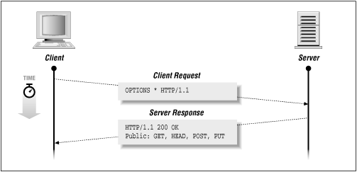
- This parameter is expected to contain the message provided by the user
- On receiving a valid parameter (message), the Server replies with a standard response acknowledging that message
- It Serial-Prints all these developments on the Serial Monitor as well

The Client:
- The Client is programmed to start by connecting to the WiFi Access Point generated by the Server. (This is hard-coded, so any change to the Access Point name on the Server code will need to be replicated on the Client code 'connect to WiFi' section)
- The Client then initializes the HTTP instance and then prompts the user for a message to send to the Server
- Once the user types and sends a message from the Serial Monitor, the Client picks it up as a String, generates a GET request with it as the value of the 'body' parameter and sends the request to the known Server IP Address (192.168.4.1 by default)
- The Client then expects a response to this request from the Server (as per the HTTP protocol)
- On receiving the response, the Client displays it on the Serial Monitor and then waits for the next message
So there you have it - a basic wireless messaging application using two ESP8266 modules.
You can extend this system by adding more Clients.
You can address each Client and Server via their IP Addresses.

Clients have the capability of sending a request, and Servers have the capability of responding to requests.
So, to make a truly bi-directional communication system, you can set up both Client and Server functionalities on each ESP8266, and use them in a non-Master/Slave arrangement.
Until then, you can play around with these codes and try out a few IoT applications!
Remember that the message being sent can be anything from a Sensor Reading to a Database Call. Your imagination is the only limit.
All our Tutorial codes and Original Product Docs are available on our Github Page.
We have plenty of more such articles on our Blog for Makers.
Track our cool projects and ideas on our Facebook Page and our Instagram Page.
Drop us questions and suggestions in the comments section below.

Comments
Post a Comment