Creating an Arduino Pong game - Arduino Tutorial
Creating arcade games is a really fun thing to do using Arduino.


At a very low cost, you can integrate all kinds of awesome interaction modules into your game.
This tutorial is about how to create the Pong game using your Arduino Uno and an 8x8 LED Matrix module.
If you haven't seen Pong before, it is a simple game where the player must bounce a ball using their paddle, ensuring that it doesn't go past the paddle. If it does, the player is out. The number of consecutive times you bounce the ball on the paddle is your score, and it shows up just after you get out.
We are going to start with a single player version of the game. I have created a Github repository, so we can grow it together from here (more on that ahead). Here is an example of what we want to build:
Parts needed
The Hardware you need to build this:
- Arduino Uno
- 8x8 LED Matrix module (with Serial SPI interface)
- Jumpers (Male-Female)
- Breadboard (optional, based on your jumpers)
 |
| Arduino Uno |
| 8x8 LED Matrix with Jumpers |
Shopping List:
- (1x) Arduino Uno - (Buy it here)
- (1x) 8x8 LED Matrix - (Buy it here)
- (1x) Jumpers Set - (Buy it here)
- (1x) Breadboard - (Buy it here)
** All the buy links point to Amazon products.
Since this page is affiliated with Amazon, we will receive a commission from Amazon for every purchase you make. You will not be charged extra. Buying it from my links will support my page and channel!
Since this page is affiliated with Amazon, we will receive a commission from Amazon for every purchase you make. You will not be charged extra. Buying it from my links will support my page and channel!
Making the Connections
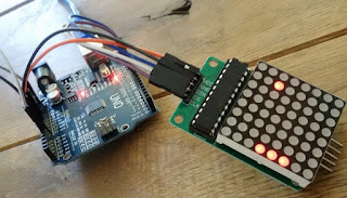
Make the connections between the Arduino and the LED matrix as in the image.
Remember, this is a serial connection using SPI.
We will be assigning pins 10, 11 and 12 for these SPI functions.
Connections:
Arduino Pin 10 - CLK of LED Matrix
Arduino Pin 11 - CS of LED Matrix
Arduino Pin 12 - DIN of LED Matrix
Arduino Pin 5V - VCC of LED Matrix
Arduino Pin Gnd - Gnd of LED Matrix
Use the Jumpers to make these connections. Connect them directly, without a breadboard if possible.
Now connect two push buttons to Pins 2 and 3.
This will be used to move the paddle left and right.
Use this connection example:
This diagram demonstrates how to connect a button to Pin 2. Do the same at Pin 3 as well.
OK. If you have this set up, your connections are ready.
We can now start programming the game.
Controlling the LED Matrix
As you can see in the 8x8 matrix, there are 8 Rows and 8 Coloumns.
To control this and set the LED values from the Serial SPI Interface, we will use a Library called LedControl.
While setting the LED values, we must set them Row-by-Row. This means that we must loop over all the Rows, setting their values as needed.
To set these values, we must imagine them as binary numbers, since LEDs have two states - HIGH and LOW. So assigning a binary number like 0b01100110 (0x66 HEX) to a Row means that the state of the LEDs in that row will be as per that binary number (LOW, HIGH, HIGH, LOW, LOW, HIGH, HIGH, LOW), in that order.
Here's an example code to set the LED Matrix Display:
#include <LedControl.h>

int DIN = 12;
int CS =  11;
int CLK = 10;

LedControl lc=LedControl(DIN,CLK,CS,0);

void setup(){
 lc.shutdown(0,false);       // Keep MAX72XX awake
 lc.setIntensity(0,15);      // Set the brightness to maximum value
 lc.clearDisplay(0);         // and clear the display
}

void loop(){
    byte a[8]=     {0x00,0xE9,0x89,0xE9,0x29,0xEF,0x00,0x00,};    byte b[8]=     {0x00,0xE7,0x94,0xE7,0x91,0xE7,0x00,0x00,};
    byte c[8]=     {0x00,0xEC,0x8A,0x8C,0x8A,0xEA,0x00,0x00,};
    byte d[8]=     {0x00,0xEE,0x49,0x4E,0x49,0xEE,0x00,0x00,};
    byte e[8]=     {0x00,0xF0,0x80,0xF0,0x80,0xF0,0x00,0x00,};    byte f[8]=     {0x00,0x66,0xFF,0xFF,0x7E,0x3C,0x18,0x00,};
    byte g[8]=     {0xFF,0x99,0x00,0x00,0x81,0xC3,0xE7,0xFF,};
    byte h[8]=     {0x00,0x66,0xFF,0xFF,0x7E,0x3C,0x18,0x00,};
    byte i[8] =    {0xFF,0x99,0x00,0x00,0x81,0xC3,0xE7,0xFF,};
    printByte(a); delay(1000);
    printByte(b); delay(1000);
    printByte(c); delay(1000);
    printByte(d); delay(1000);    printByte(e); delay(1000);    printByte(f); delay(1000);
    printByte(g); delay(1000);
    printByte(h); delay(1000);
    printByte(i); delay(1000);
    lc.clearDisplay(0);
    delay(1000);
}

void printByte(byte character [])
{
  int i = 0;
  for(i=0;i<8;i++)
  {
    lc.setRow(0,i,character[i]);
  }
}
So now you know how to control the LED Matrix.
The next step will be designing the game using it.
Defining Positions, Movements & Physics
As you saw, the entire LED Matrix can be defined with a Byte Array like:
byte display[8] = {0xFF,0x99,0x00,0x00,0x81,0xC3,0xE7,0xFF,};To define the ball's position and speed, it is important to be able to translate the Co-ordinates to this Byte Array notation.
That is quite simple, since this Byte Array notation actually uses a similar logic, only in binary. So if our ball position is x, y and we want to display it on the LED Matrix, we do:
display[y] = 2^(7-x) // x can go from 0 to 7 here
display[5] = 2^(4) // 0b00010000 on the 5th Row - for position (3,5)
Our calculations will be in the Co-ordinate notation using X and Y directions. (0,0) is taken as the bottom left corner.
Speeds can be defined as vertical and horizontal speed components.
Assuming a constant value for speed in any of these directions, we can define them with two integers: X Speed and Y Speed.
Note that these Speeds can work together to provide diagonal movement. Now, X Speed and Y Speed will only take values 1, 0 and -1 for simplicity. But you can later upgrade your project to have variable speeds as levels progress.
For this example, we will use the values of these speeds to define which direction the ball moves in on every loop. So a X Speed as -1 means that the ball moves one pixel in the negative X direction (left) for every loop. Coupled with a Y Speed of -1, this would mean that the ball moves one pixel downwards as well, resulting in diagonal motion.
Being a simple example, the Physics here are restricted only to ball interactions with the edges of the Matrix and the user's Paddle. We will program the ball to 'bounce off' walls as well as the user's paddle with no change in speed, but only in direction. This means that if the ball hits a vertical wall, it's horizontal speed is inverted and if the ball hits the ceiling or Paddle, it's vertical speed is inverted. all we need to do here is multiply the corresponding Speed by -1.
speedX=speedX*(-1) // Inverting Speed in X direction when bouncing off walls
Gamification
This is where you define the points system. How does a user know how well they have done inn the game?
Here we will award one point to a user each time they bounce the ball off their paddle.
So when they finally get out, they can be shown their score.
points++; // When the ball touches the user's paddleWe should also know when the ball has gone past the user's paddle. To do this, we check the ball's trajectory when it reaches the second-last Row, because the paddle is on the last Row. We know it's position on the second-last Row and also it's speed. Using this, we calculate the position of the ball when it reaches the last Row. If this calculated position is taken up by the paddle, it means that the ball will bounce off safely.
If not, we can conclude that the ball goes past the paddle and the player is out. The game also freezes here. It can be restarted by pressing the Arduino reset button.
User Interaction
The User Interaction here is quite simple. There are just two buttons that the User presses to move the paddle left or right. So we integrate them into the project by declaring them as INPUT GPIOs. Add these lines to the setup() function.
pinMode(2, INPUT); // declaring Pin 2 as inputpinMode(3, INPUT); // declaring Pin 3 as input
Putting it all together
Using these components of the game, we can put them together and have a basic version of the game running with the Arduino. Remember, you can always make modifications, change parts and experiment with this. Use this simply as a starting point for your project.
We are using the LedControl Library. You can get it here. Or install it from the Arduino IDE's Library manager in Sketch->Libraries
The final code combines all the parts discussed above and lays down a basic pong game that you can build on.
The complete shopping list is linked above. Do check that out if you need to buy any parts.
Get the full code here on Github.
This is a basic version where we can start from. Please go ahead, fork and update the code. Leave comments on the Github page as well for suggested updates.
I'm glad to get this code off the ground and hope we can grow it together. Go on and build something awesome. Don't forget to share the work you do!

This comment has been removed by the author.
ReplyDeleteThis comment has been removed by the author.
ReplyDelete